This document describes five of the most basic 4 to 20 mA current loop configurations:
1. A two-wire transmitter with external power and an external resistor
2. A two-wire transmitter with controller power and a 4 to 20 mA input
3. A two-wire transmitter with external power and a 4 to 20 mA input
4. A three-wire transmitter with one 4 to 20 mA signal
5. A three-wire transmitter with two independent 4 to 20 mA signals.
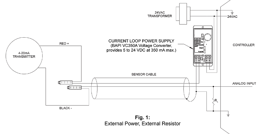
1. External Power, External Resistor
Many low cost HVAC/R controllers do not include a dedicated power supply or a factory configured input for a 4 to 20 mA signal. At the same time, many of the best sensors in the industry are only available as a 4-20 mA output. Figure 1 below shows how to create a 4 to 20 mA current loop circuit for a controller without a dedicated power supply or an input for a 4 to 20 mA signal.
A 24 VAC transformer provides power to the controller and the BAPI VC350A voltage converter used in the example below as the current loop power supply. The VC350A should be mounted as close as possible to the controller. The positive output of the VC350A is connected through a cable to the Red or positive terminal of the transmitter. The Black or signal terminal of the transmitter is connected to the controller’s analog input. The shield of the cable is connected to the controller ground and the negative terminal of the VC350A. A load resistor is connected from the analog input to ground. If the controller’s analog input is configured for 0 to 5 VDC, then the load resistor should be 250Ω. The signal voltage will be 1 volt at 4 mA and 5 volts at 20 mA. If the controller’s analog input is configured for 0-10 VDC, then the load resistor should be 500Ω. The signal voltage will be 2 volt at 4 mA and 10 volts at 20 mA.
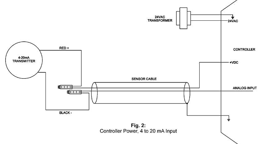
2. Controller Power, 4 to 20 mA Input
Many larger controllers have DC power supplies to power sensor peripherals and also have dedicated 4 to 20 mA inputs. Figure 2 shows how to create a 4 to 20 mA current loop circuit for this style of controller.
A 24 VAC transformer provides power to the controller. The VDC output of the controller is connected through a cable to the Red or positive terminal of the transmitter. The Black or signal terminal of the transmitter is connected to the controller’s analog input which is factory configured to accept a 4 to 20 mA signal. The shield of the cable is connected to the controller ground.
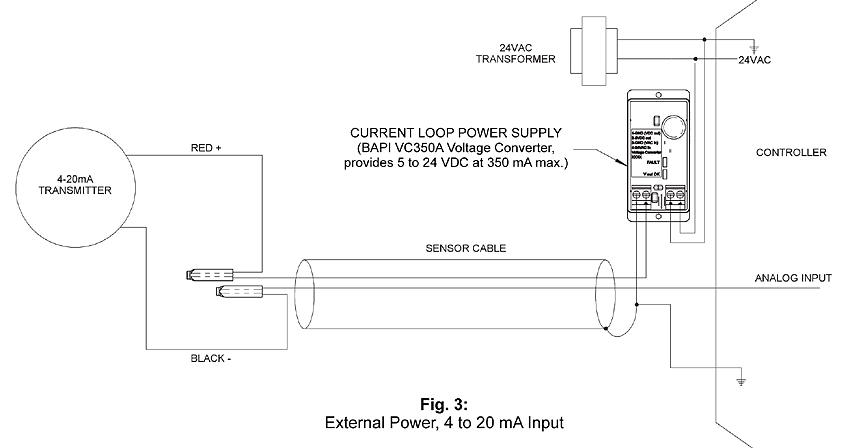
3. External Power, 4-20 mA Input
The larger controllers that have DC power supplies to power sensor peripherals cannot supply unlimited power. When the controller’s peripheral power supply current limit is reached, an external power supply is needed to power additional sensors. Figure 3 shows how to create the 4-20 mA current loop circuit for this particular circumstance.
A 24 VAC transformer provides power to the controller and BAPI VC350A voltage converter used in the example below as the current loop power supply. The VC350A should be mounted as close as possible to the controller. The positive output of the VC350A is connected through a cable to the Red or positive terminal of the transmitter. The Black or signal terminal of the transmitter is connected to the controller’s analog input which is factory configured to accept a 4-20 mA signal. The shield of the cable is connected to the controller ground and the negative terminal of the VC350A.
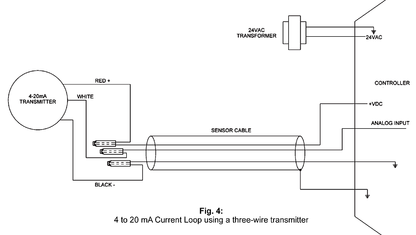
4. Three-Wire Transmitter with One 4 to 20 mA Signal
Some of BAPI’s current transmitters are three-wire devices, such as the BAPI-Stat room unit. Three-wire transmitters are supplied with power and ground separate from the 4 to 20 mA current signal. The transmitter contains a current source that provides signal current proportional to the physical property being measured. The three-wire transmitter’s common must be connected to the controller’s common.
Figure 4 shows the most basic three-wire transmitter with one 4 to 20 mA signal. Unlike a two-wire transmitter, a three-wire transmitter will consume more current from the system power supply than the 20 mA signaling current because the transmitter itself requires some current to operate. For instance, the BAPI-Stat three-wire transmitter requires 10 mA of current to operate. If the transmitter in the circuit below is a BAPI-Stat, and the signal current (the white wire) is at 4 mA, then the total current from the power supply is 14 mA. When the signal current is at 20 mA, the total current from the power supply is 30 mA.
Remember that the controller may not have enough capacity to power the sensor, therefore an external power supply may be necessary.
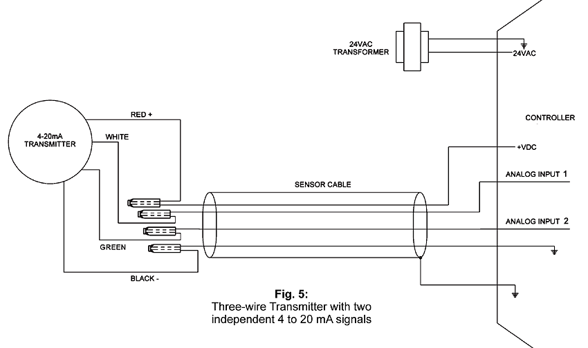
5. Three-Wire Transmitter with Two Independent 4 to 20 mA Signals
Three-wire transmitters may have more than one 4-20 mA output signal. The BAPI-Stat room unit is a good example; it contains two independent 4-20 mA transmitters. As in the previous example, three-wire transmitters are supplied with power and ground and contain a current source that provides loop current proportional to the physical properties that are being measured. The three-wire transmitter’s common must be connected to the controller’s common.
Figure 5 shows a 3-wire transmitter with two 4-20 mA signals. Unlike a two-wire transmitter, a three-wire transmitter will consume more current from the system power supply than the two 4-20 mA signals alone because the transmitter itself requires some current to operate. For instance, the BAPI-Stat three-wire transmitter requires 10 mA of current to operate. If the transmitter in the circuit below is a BAPI-Stat, and both signal currents are at 4 mA, then the total current from the power supply is 18 mA. When the signal currents are at 20 mA each, the total current from the power supply is 50 mA.
Remember that the controller may not have enough capacity to power the sensor, therefore an external power supply may be necessary.
If you would like more indepth information about ground loops, call your BAPI representative or see the BAPI Application Notes: “Designing 4 to 20 mA Current Loops” and “The Science Behind 4 to 20 mA Current Loops” from this website.
Reference
ANSI/ISA-50.1-1982 (R1992) Compatibility of Analog Signal for Electronic Industrial Process Instruments. (This document is the industry specification for 4-20mA current loop signaling.)