This document describes the danger of mixing half wave and full wave power supplies and also gives an overview of the basic half wave and full wave power supply circuits.
Diodes
To understand the difference between full and half wave power supplies, you have to understand how a diode works.
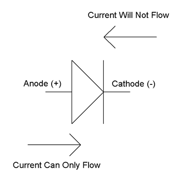
Figure 1 shows the schematic symbol used for a diode. A diode is an electronic switch. When the anode (+) terminal has a more positive voltage on it than the cathode (-) terminal, the switch is closed and current will flow through the diode from anode (+) to cathode (-). When the cathode (-) terminal has a more positive voltage on it than the anode (+) terminal, the switch is open and current will not flow.
The Danger of Mixing Half Wave with Full Wave Power Supplies
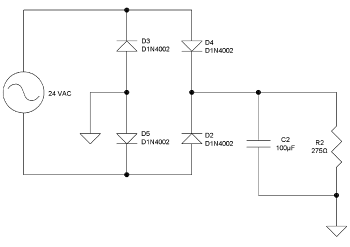
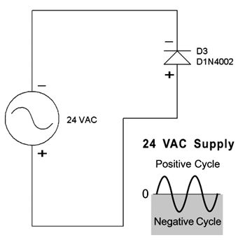
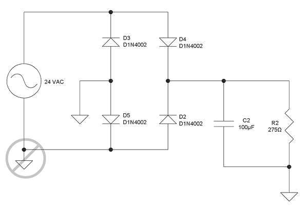
Figure 2 shows a full wave power supply schematic. Many control systems use half wave power supplies, and in these systems, the bottom terminal of the 24VAC transformer is typically connected to ground. If a full wave power supply is connected to such a system (as shown in Figure 4), then the top terminal of the transformer is also connected to ground through diode D3 during the negative half cycle of the VAC power supply. This creates a short between the transformer terminals (as shown in figure 3) which will either trip a circuit breaker, burn out the diode or burn out the transformer – or possibly all three.
Therefore you should never try to power half wave power supplies and full wave power supplies from the same transformer.
Half wave and full wave power supplies can coexist in the same control system, they just have to be powered by separate transformers.
Half Wave Power Supplies
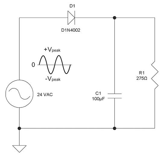
Figure 5 shows a simple half wave power supply. 24VAC is the output of a 24VAC power transformer. D1 is the diode that changes the AC into pulsating DC. C1 is a filter capacitor that smoothes the pulsating DC. R1 is the circuit load, 275Ω was chosen for a load of about 100mA.
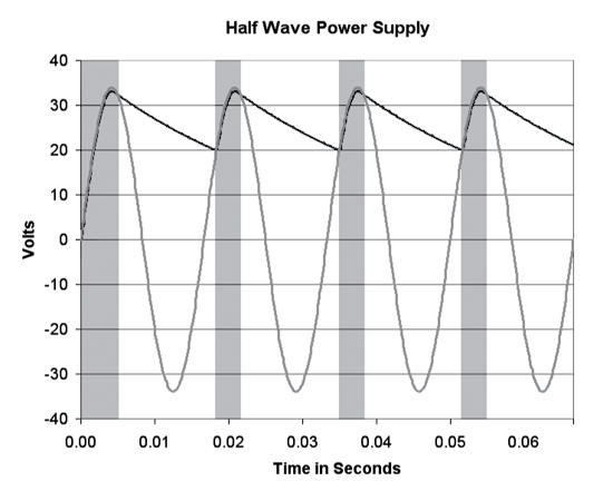
Figure 6 shows the voltage waveforms of the half wave power supply when the input is 24 VAC RMS (or 68 volts peak-to-peak). The lighter waveform is the 24 VAC supply and the darker waveform is the voltage across the filter capacitor C1 and load resistor R1.
As indicated in Fig. 6, on every positive half cycle of the 24 VAC supply, the voltage across the filter capacitor and load resistor rises to the peak value of the AC voltage. On the negative half cycle, the capacitor provides the current for the load. The variation in the load voltage, or ripple, is dependent upon the capacitor value – a larger capacitor will have less voltage ripple.
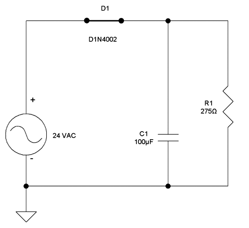
During the shaded portion of Fig. 6, the effective schematic of the half wave power supply is shown in Figure 7. The 24 VAC supply is charging up C1 and supplying load current. Since the capacitor has to store up current for the negative half cycle, the capacitor charging current can be quite large, in this case almost 1 amp. The larger the capacitor, the larger the charging current.
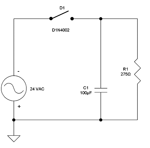
During the unshaded portion of Figure 6 the effective schematic of the half wave power supply is shown in Figure 8. The diode is open, so the 24 VAC source is not supplying any power and the capacitor is supplying all the load current.
Half wave power supplies are usually more complicated than the circuit shown in Figure 5. This simple circuit was chosen for easy explanations. Usually there is a regulation circuit to keep the output at a constant voltage. Regulators work well but they cannot hold a constant output if the filter capacitor voltage falls below the regulated output. Regulators also use some of the filter capacitor voltage to work correctly.
In the circuit shown here, the filter capacitor’s voltage falls to 20 volts before it is recharged by the 24 VAC. Therefore, it would be impossible to have a regulated output greater than 19.5 VDC.
Full Wave Power Supplies
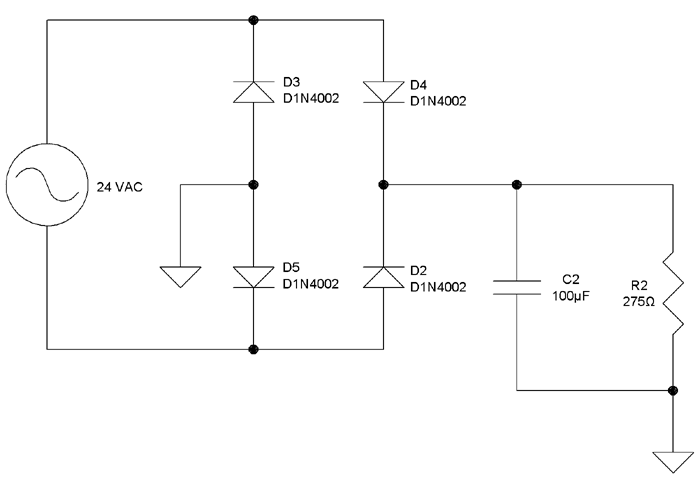
Figure 9 shows a simple full wave power supply. 24VAC is the output of a 24VAC power transformer. D2, D3, D4 and D5 are the diodes that change the AC into pulsating DC. C2 is the filter capacitor that smoothes the pulsating DC. R2 is the circuit load, 275Ω was chosen for a load of about 100mA.
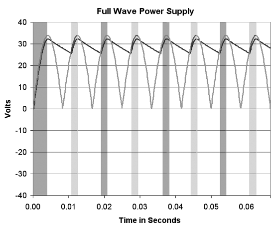
Fig. 10 shows the voltage waveforms of the full wave power supply when the input is 24 VAC RMS (or 68 volts peak-to-peak). The lighter waveform is the 24 VAC supply after it has been converted to pulsating DC voltage by the diodes. The darker waveform is the voltage across the filter capacitor C2 and load resistor R2.
As indicated in Fig. 10, the voltage across the filter capacitor and load resistor rises to the peak value of the supply voltage. As the supply voltage heads back towards zero, the capacitor provides the current for the load. The variation in the load voltage, or ripple, is dependent upon the capacitor value – a larger capacitor will have less voltage ripple.
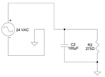
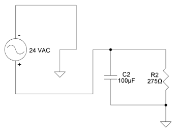
During the dark shaded boxes of Figure 10, the effective schematic of the power supply is shown in Figure 11. During the light shaded boxes of Figure 10, the effective schematic of the power supply is shown in Figure 12. During both of these periods, the 24 VAC supply is charging up C1 and supplying load current. Capacitor charging current can be quite large, in this case almost 0.5 amp. The larger the capacitor, the larger the charging current.
During the unshaded portion of Figure 10, all the diodes are open and the capacitor is supplying all the load current.
Full wave power supplies are usually more complicated than the circuit shown in Figure 9. This simple circuit was chosen for easy explanations. Usually there is a regulation circuit to keep the output at a constant voltage. Regulators work well but they cannot hold a constant output if the filter capacitor voltage falls below the regulated output. Regulators also use some of the filter capacitor voltage to work correctly. In the circuit shown on the previous page, the filter capacitor’s voltage falls to 25.5 volts before it is recharged by the 24 VAC. Therefore, it would be impossible to have a regulated output greater than 25 VDC.
As described on the first page of this document, half wave and full wave power supplies can coexist in the same control system, they just have to be powered by separate transformers.
If you have additional questions about half wave and full wave power supplies, please call your BAPI representative.