Thermowells are hidden in pipes and are rarely seen. How dimensions are established for the thermowells and the immersion probes that fit into them are not readily apparent. This application note explains how the dimensions are defined, how to install thermowells and immersion probes and defines their application environment.
What are Thermowells?
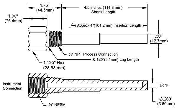
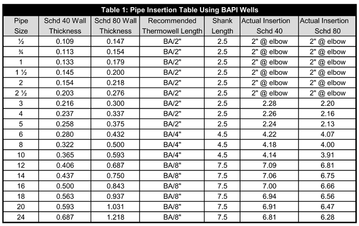
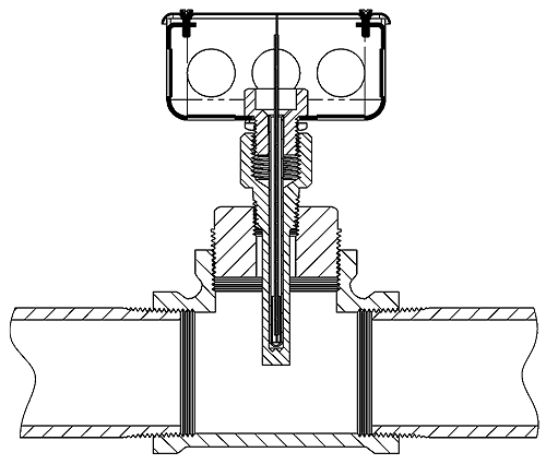
Thermowells are hollow tubes closed off on one end and threaded at the other end. They are permanently placed into pipes, tanks or sumps so that temperature measurement probes can be inserted into them to measure the contents temperature. The temperature of the content is transferred through the wall of the thermowell to the temperature measurement probe. The thermowell prevents the content of the pipe from escaping and holds in the pressure of pressurized pipes. Thermowells are sold by insertion length, which is the length of the thermowell inside the pipe. Fig 1 shows a 4” thermowell; notice that the 4” dimension is an approximate insertion length that is based on a schedule 80, 8” diameter pipe (see Table 1 and Fig 2).
How Thermowells and Immersion fittings are installed.
General Information
Immersion probes need to be at least two inches longer than the shank length to fit through all the fittings at the open end of the thermowell. Immersion probes come with a fitting that threads into the top of the thermowell. BAPI’s standard immersion probe fitting holds the probe with a tight friction fit. Double threaded probes are designed to bottom out in the thermowell when tightened.
Pull the probe out of the enclosure until the flare on the end of the probe, where the sensor wires come out, touches the immersion fitting. Insert the probe into the thermowell and push the immersion fitting towards the thermowell until the fitting’s threads engage the thermowell. Screw in the immersion fitting until it is just finger tight. The probe will move away from the immersion fitting surface into the enclosure. Carefully push on the temperature probe flair to be sure that the end of the temperature probe is bottomed out in the thermowell. The friction between the probe and the immersion fitting holds the probe against the bottom of the thermowell and ensures good temperature transfer.
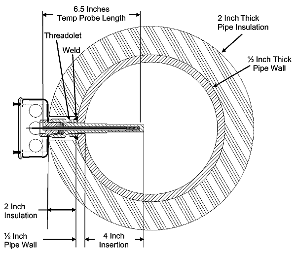
Fig 2 shows a 4” thermowell and 4” immersion probe installed into an 10” pipe. In a properly insulated pipe with liquid or steam, the temperature is essentially the same across the entire cross section of the pipe. Usually thermowells are sized to extend to the center of the pipe; however, shorter thermowells will give proper temperature readings if properly installed. Shorter thermowells are used in pipes with high flow velocities, see Table 3.
In practice, a 0.75” hole is drilled into the pipe where the thermowell is needed. A fitting, called a threadolet, is welded over the hole. A thread sealant such as Teflon tape or pipe dope is applied to the outside threads of the thermowell. The thermowell is inserted into the threadolet and tightened. Since the wall thickness of the pipe commonly used for HVAC plumbing is 0.5”, the thermowell sticks four inches into the pipe. The 4” distance called out by a 4” thermowell is the distance from the inside surface of the pipe to the end of the thermowell.
Pipes Three Inches in Diameter and Larger
Figure 2 shows a four-inch thermowell and four-inch immersion probe installed into an eight inch pipe. In a properly insulated pipe with liquid or steam, the temperature is essentially the same across the entire cross section of the pipe. Usually thermowells are sized to extend to the center of the pipe; however, shorter thermowells will give proper temperature readings if properly installed. Shorter thermowells are used in pipes with high flow velocities, see Table 3.
In practice, a ¾-inch hole is drilled into the pipe where the thermowell is needed. A fitting, called a threadolet, is welded over the hole. A thread sealant such as Teflon tape or pipe dope is applied to the outside threads of the thermowell. The thermowell is inserted into the threadolet and tightened.
Since the wall thickness of the pipe commonly used for HVAC plumbing is ½-inch, the thermowell sticks four-inches into the pipe. The four-inch distance called out by a four-inch thermowell is the distance from the inside surface of the pipe to the end of the thermowell.
Pipes Less Than Three Inches in Diameter
Fig 3 shows how a pipe tee can be used in an elbow application. A 2” tee and a 0.5” to 2” bushing allows a 4” thermowell to measure the temperature of the contents of a 2” water pipe. Temperatures in pipes as small as 1.25” may be measured by this method. In small pipes, the diameter of the thermowell may become a significant obstruction, so be sure to check for proper flow rates.
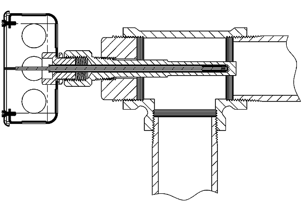
Alternatively, Fig 4 shows how a 2” tee and a 0.5” to 2” bushing allows a 2” thermowell to measure the temperature of the contents of a 2” water pipe. Be sure to use a thread sealant on the outside threads of the thermowell.
Types of Thermowells
BAPI sells machined brass, machined stainless steel and two-part welded stainless steel thermowells.
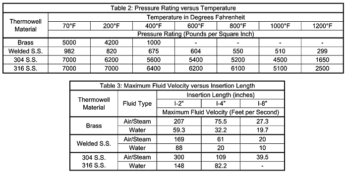
Two-part welded stainless steel thermowells are not as strong as their machined counterparts. See the entries for Welded stainless steel (S.S.) in the following design tables. Additionally, welded stainless steel thermowells should not be used in turbulent flow; ideally they should be three to five pipe diameters from elbows or transitions.
Shake, Rattle & Roll
Tables 2 and 3 were developed to ensure that there will be no thermowell failures due to application stresses. Thermowell failures, in most cases, are not due to the effects of pressure or temperature on the thermowell. The calculations necessary to provide adequate strength, under given conditions, are familiar enough to permit proper choice of wall thickness and material. The values shown in Table 1 are conservative, and intended primarily as a guide.
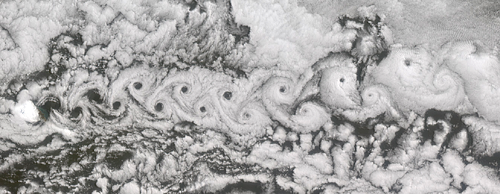
Less familiar, and more dangerous, are the vibration effects to which thermowells are subjected. Fluid, flowing by the thermowell, forms a turbulent wake (called the Von Karman Trail) which has a definite frequency, based on the diameter of the thermowell and the velocity of the fluid. It is important that the thermowell have sufficient stiffness so that the wake frequency will never equal the resonant (natural) frequency of the thermowell itself. If the resonant frequency of the thermowell coincided with the wake frequency, the thermowell would vibrate to destruction and break off in the piping.
Von Karman Trails form as the fluid flows around the thermowell. First the fluid swirls clockwise and then counterclockwise. The swirls form low pressure regions behind the thermowell and the total fluid pressure pushes the thermowell back and forth. Thermowells are also safe if the resonant frequency is well below the wake frequency or if the fluid velocity is constantly fluctuating through the critical velocity point.
Fig 5 is a picture taken by NASA’s Multi-angle Imaging SpectroRadiometer satellite on June 6, 2001. A Von Karman Trail extends over 300 km southward of Jan Mayen Island (North is to the left in Fig 5). Jan Mayen is an isolated island of Norway, located about 650 km northeast of Iceland in the North-Atlantic Ocean. Jan Mayen’s Beerenberg volcano rises about 2.2 km above the ocean surface, providing a significant impediment to wind flow.
As each vortex is generated, a low pressure region develops on alternate sides of the volcano. The volcano is pushed slightly back and forth with each vortex. Similar vortexes are generated by fluids flowing down a pipe with a thermowell in it. The thermowell vibrates just like a tuning fork, and at a critical frequency the thermowell will break off in the pipe. Using the recommendations in Tables 2 and 3 helps ensure that you do not have any such problems for the life of your system.
If you have any questions, please call your BAPI representative.