Warning: BAPI DOES NOT recommend using Duct Averaging sensors in freeze stat (low/high limit switch) applications.
Overview:
It can be difficult to measure the actual temperature of air within a duct when that air is separated into layers with different temperatures, called stratified air. This stratification occurs most often in the mixing chamber or section of duct where the Return Air (RA) from a room is mixed with the new Outside Air (OSA) brought into the system. The stratification is usually side to side (horizontal stratification) or top to bottom (vertical stratification) although it can sometimes be at a 45 degree angle. The type of stratification can be determined by inserting different colored smoke into the RA and OSA air streams to see how it flows through the mixing chamber.
Knowing the temperature of this stratified air is crucial for good energy management and comfort control. Depending on the location of the sensor and size of the duct, a single point duct sensor may not provide a true representation of the temperature within the duct. A duct averaging sensor is a common way to measure the average temperature of the stratified air.
Thermistor vs RTD Averaging Sensors
RTD Sensors — RTDs are built as continuous wire strands that measure an average temperature along their entire length without gaps between the sensing elements. The resistive signal from the RTD can be wired directly to the BAS or it can be converted to a current (4 to 20mA) for the BAS.
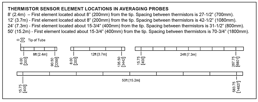
Thermistor Sensors — Thermistors are multi-point discrete sensing elements. Therefore an averaging unit with thermistor sensors will have up to nine individual thermistors installed in the tube at different points along the length. The flexible copper or aluminum tube conducts the temperature along the length to the nearest sensor inside the tube. The individual thermistors are wired together in a series/parallel configuration to provide a single average temperature resistive signal to the BAS.
Averaging Sensor Mounting Methods
Averaging probes are available as flexible or rigid. Flexible averaging probes are made of bendable aluminum or copper tubing and can be bent back and forth within the duct. Rigid averaging probes run across the height or width of the duct in a straight line. Because of the different ways that air can stratify, there are a number of different averaging sensor mounting methods. The following are mounting “Rules of Thumb” that can be used as starting points to achieve the best temperature reading with an averaging sensor.
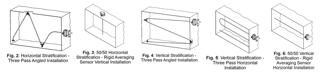
Horizontal Stratification — If you have horizontal stratification, then install the sensor vertically (up and down) across the duct through the lines of stratified air (See Figs 2-3). On an angled installation as in Fig. 2, have the same number of passes on each side of the stratification to evenly represent all the air in the duct.
Vertical Stratification — If you have vertical stratification, then install the sensor horizontally (side to side) across the duct through the lines of stratified air (See Figs 4-6). On an angled installation as in Fig. 4, have the same number of passes on each side of the stratification to evenly represent all the air in the duct.
Unknown or Complex Stratification — If the type of stratification is unknown or complex, then install the averaging sensor at a 45º angle across the duct (similar to Figs 2 or 4) to give the best possible result. Have the same number of passes on each side of the duct to evenly represent all the air in the duct.
Formula 1:
One averaging sensor pass for every 10 square feet of duct size, rounded up to the next pass.
Example: 9’x9’ square duct equals a duct size of 81 square feet, so 81/10 = 8.1
The 8.1 is rounded up to 9, so this application should have a minimum of 9 passes across the duct.
Formula 2:
One averaging sensor pass for every 1 foot diameter across the duct, rounded up to the next foot.
Example: 9’x9’ square duct equals a diameter of 9 ft.
So this application should have a minimum of 9 passes across the duct.
Installation Best Practices
For flexible averaging sensors, keep each turn gradual and avoid kinks by using a BAPI Flexible Probe Bracket (FPB) at each turn.
If averaging sensors pass each other (such as a crisscross pattern), be sure to tie wrap the two passing sensors to avoid tapping and excessive rubbing that could lead to noise and premature failure. Averaging sensors installed with spans greater than four feet should be supported mid-duct or every four feet to avoid resonant movement as air passes, which can cause sensor metal fatigue and premature failure.
For more information about the Averaging Sensors, contact a BAPI key account specialist at +1-608-735-4800.