Resistance Temperature Detectors (RTDs) are devices used to measure temperature in modern Heating, Ventilation, Air Conditioning and Refrigeration (HVAC/R) systems. This application note compares the 100Ω Platinum RTD to the 1KΩ Platinum RTD and will explain why the 1KΩ is superior to the 100Ω for measuring temperature in a modern HVAC/R system.
Specifically, the paper will describe how:
• The larger resistance change with temperature change allows 1KΩ RTDs to measure small changes in temperature with more resolution;
• The larger resistance change with temperature change allows 1KΩ RTDs to have longer sensor leads;
• The larger resistance change with temperature change allows 1KΩ RTDs to have less amplification of electrical noise.
RTD BACKGROUND
Metals increase in resistance with an increase in temperature and RTDs are metal-based temperature sensors that exploit this resistance change. RTDs can be made from many different metals to measure temperature (see Table 1).
The temperature coefficient of resistance is defined as the resistance of the RTD at 100°C minus the resistance at 0°C divided by 100, then divided by the RTD’s resistance at 0°C. This translates as the average resistance change per °C from 0 to 100°C.
Copper has the most linear change in resistance for a given temperature change. However, copper’s low resistance makes it difficult to measure small changes in temperature. Nickel has a large change in resistance with temperature change, but nickel is not a very stable material and its resistance varies considerably from batch to batch. While nickel is much less expensive than platinum, the added processes needed to stabilize nickel’s resistance makes nickel RTD sensors more expensive than platinum.
Platinum has become the defacto standard in precision thermometry. It has a reasonably high resistance, has a good temperature coefficient, does not react with most contaminant gasses in air and is extremely stable from batch to batch.
The 100Ω Platinum RTD has been commercially available since the 1920s. Early RTDs were manufactured by winding a long, thin platinum wire around a substrate. Platinum wire used for RTDs is very thin and brittle, making wire wound RTDs difficult to produce. The 100Ω RTD was originally proposed as a compromise between the cost of Platinum wire, the size of the sensor element body and high enough resistance to make a useable measurement. The average resistance change from 0 to 100°C is 0.385 Ω/°C.
The 1KΩ Platinum RTD has been commercially available since the 1960s. Most 1KΩ RTDs are manufactured from a thin platinum film deposited on a ceramic substrate. The platinum film is patterned to be a long thin line. The average resistance change from 0 to 100°C is 3.85 Ω/°C.

RTD Resistance Change and Temperature Measurement Resolution
Because the 1KΩ RTD’s resistance change of 3.85Ω per °C is ten times greater than the 100Ω RTDs change of 0.385Ω per °C, it is much easier to measure a small change in temperature. Many HVAC systems are designed to hold space temperature to within 1°F. To achieve such performance, the HVAC controller must be able to resolve temperature changes as small as 0.1°F. A 0.1°F change in a 1KΩ RTD is the same resistance change as a 1°F change in a 100Ω RTD. The universal inputs of most modern DDC controllers only measure 1KΩ RTDs for better resolution.

Sensor Lead Length and Its Effect on RTD Accuracy
The larger resistance change with temperature change allows 1KΩ RTDs to have longer sensor leads.
A transmitter or universal input converts the total resistance connected to its inputs to a temperature value. This total resistance includes the resistance of the RTD plus the resistance of the lead wires connecting the RTD to the transmitter or universal input. Table 2 provides the resistance of various sizes of annealed copper wire at 70°F (21.1°C) and the temperature offset error per foot that this lead wire would have on a 100Ω and a 1KΩ RTD.
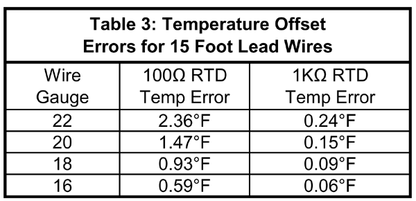
If 15 feet of wire connects the RTD to the transmitter, the total wire length is 30 feet – 15 feet out and 15 feet back. Table 3 shows the actual temperature error that this 15 feet of lead wire would cause on a 100Ω and 1KΩ RTD.
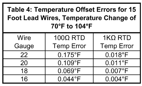
The figures in Table 3 are based on a temperature of 70°F (21.1°C); however, the resistance of copper wire changes with temperature. Many equipment rooms are not conditioned so they can often reach temperatures as high as 104°F. Table 4 shows the additional temperature offset error due to the sensor leads changing from 70°F to 104°F.
In practice the errors shown in Table 4 would be added to the errors shown in Table 3. While the Table 3 errors can be largely eliminated by purchasing a matched RTD/transmitter pair, Table 4 errors cannot.
Most HVAC/R applications can withstand .25°F offset errors. To stay within this range while using a 100Ω RTD, the sensor leads would need to be 18 inches or shorter. To stay within this range while using a 1KΩ RTD, the sensor leads could be up to 15 feet long.
The Antenna Effect and Noise Amplification
Transients and radiated electrical noise signals abound in modern buildings and spread through the air like radio waves. RTDs make great antennas and pick up some of this noise. Broadcast engineers know that the optimum resistance for an antenna to receive a signal is 377Ω. A 100Ω RTD’s resistance is a lot closer to 377Ω than the resistance of a 1KΩ RTD. Electrical noise spreading through the air will couple with a greater signal level into a 100Ω RTD than a 1KΩ RTD.
Besides picking up more of the noise signal, the resistance change of the 100Ω RTD is 1/10th the resistance change of the 1KΩ RTD. Therefore the RTD resistance and the noise signal is amplified ten times more in a circuit with a 100Ω RTD than it would be in a circuit with a 1KΩ RTD. That means a 100Ω RTD has the double disadvantage of larger induced noise signals and greater amplification of the induced noise, creating larger offset error in the temperature measurement.
If you have any additional questions about the 100Ω and 1KΩ Platinum RTDs, please call or email your BAPI representative.